
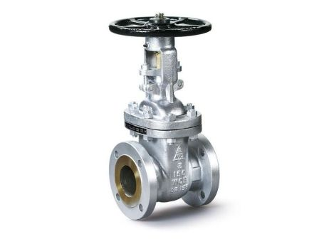
Gate Valve
GTF-600
Full BoreCLASS 600
2" ~24" DN50~DN600
API600 Cast Steel Gate Valves |
|---|
1. API600 GTF-600 |
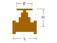
| Dimensions |
| Please refer to the Dimensions section. |
 |
| Measurement Units |
| 1. All lengths are measured in millimeter and inch. 2. All weights are measured in kilograms and pounds |
| About Product |
| 1. Shipping and Tax are not included in pricing. 2. All products supplied by Modentic are under products liability insurance. 3. Valvebus.com reserves the rights to change any details without prior notice. |
| About VALVEBUS |
| VALVEBUS.com reserves the right to change any details without prior notice. |
| Back to Top |
| MODEL | GTF-600 |
| PRODUCT TYPE | API600 Cast Steel Gate Valves |
| OPERATION | Handwheel |
| PRESSURE | CLASS 600 |
| CONNECTION | Flanged End |
| PORT | Full Bore |
| BODY Material | ASTM A216 Gr.WCB |
| CAP / BONNET Material | ASTM A216 Gr.WCB |
| STEM Material | SS316 |
| DISC Material | ASTM A216 Gr.WCB |
| SEAT Material | - |
| SEAT RING Material | SS316 |
| BODY SEAL Material | SS304 + GRAPHITE |
| SAMPLE CASTINGS |
| Before castings are released for production, the Modentic NDE inspector Level III, evaluates and approves the submitted x-ray films (100% Coverage) as per ASME B16.34 acceptance standard. Improves the intermal integrity of castings (RT Level 2 or better) at pattern approval |
| API600 GTF-600 |
| STANDARD COMPLIANCE • API600 • ASME / ANSI B16.34 • ASME/ANSI B16.10 Class 600 RF • ASME/ANSI B16.10 Class 600 BWF • ASME/ANSI B16.5 Class 600 RF, Finish 125-250 AARH • ASME / ANSI B16.25 • API598 OPTION • Universal Trim 13 Cr Srem, Wedge 13 Cr Face and StellitedSeat, API Trim 8 Suitable for Application up to 850°F (454°C) |
| FLEXIBLE WEDGE |
| A wedge design flwo control element of a gate valve made of a singple piece that has a groove arround its perimeter to provide flexibility and some movement of its seating surface; also called a flex wedge |
| Flanged End |
| END CONNECTION STANDARD ANSI B16.5 / EN1092 VALVES LENGTH STANDARD ANSI B16.10 / DIN3202 F1 / F4 / F5 |
| SIZE NPS |
E mm |
H mm |
L mm |
WEIGHT kgs |
| DN50 | 165.1 | 458.0 | 295.0 | - |
| DN65 | 190.5 | 508.0 | 333.0 | - |
| DN80 | 209.5 | 570.0 | 359.0 | - |
| DN100 | 273.0 | 657.0 | 435.0 | - |
| DN150 | 356.0 | 872.0 | 582.0 | - |
| DN200 | 419.0 | 1101.0 | 664.0 | - |
| DN250 | 508.0 | 1279.0 | 791.0 | - |
| DN300 | 558.8 | 1466.0 | 841.0 | - |
| DN350 | 603.2 | 1623.0 | 892.0 | - |
| DN400 | 685.8 | 1816.0 | 994.0 | - |
| DN450 | 742.9 | 2260.0 | 1095.0 | - |
| DN500 | 812.8 | 1705.0 | 1200.0 | - |
| DN600 | 939.8 | 2810.0 | 1407.0 | - |
| SIZE Inch |
E Inch |
H Inch |
L Inch |
WEIGHT lbs |
| 2" | 6.5 | 18.0 | 11.6 | - |
| 2-1/2" | 7.5 | 20.0 | 13.1 | - |
| 3" | 8.2 | 22.4 | 14.1 | - |
| 4" | 10.7 | 25.9 | 17.1 | - |
| 6" | 14.0 | 34.3 | 22.9 | - |
| 8" | 16.5 | 43.3 | 26.1 | - |
| 10" | 20.0 | 50.4 | 31.1 | - |
| 12" | 22.0 | 57.7 | 33.1 | - |
| 14" | 23.7 | 63.9 | 35.1 | - |
| 16" | 27.0 | 71.5 | 39.1 | - |
| 18" | 29.2 | 89.0 | 43.1 | - |
| 20" | 32.0 | 67.1 | 47.2 | - |
| 24" | 37.0 | 110.6 | 55.4 | - |